A UML use case diagram is composed of the following symbols:
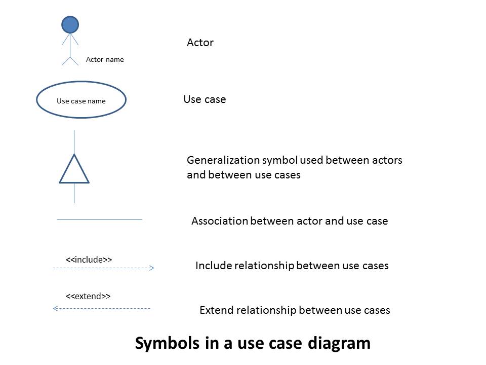
Figure 1. Symbols used in a use case diagram
Actor: An actor represents an external entity that interacts with a system. Since it is external to the system, the actor itself is not fully modeled by the system. However, in order to design the interactions between an actor and a system, the latter may have a simplified model of the actor. A user of a system is a typical example of an actor. Other types of actors include software systems that are being integrated with the current system (e.g., a network protocol, a database system, a file system), external hardware such as a sensor and so on.
Actors are classified into primary actors (also called active actors) and secondary actors (also called passive actors). Primary actors initiate a use case and hence are somewhat independent. Secondary actors, on the other hand, are used by the system but they do not interact with the system on their own. In other words, secondary actors do not initiate any use case. The symbol for an actor does not differentiate between a primary actor and a secondary actor; the difference must be inferred from the use case descriptions (also called use case narratives).
An actor represents the role of the entity that interacts with the current system, not an instance. For example, an actor may represent a customer of a bank. In this case, every customer of a bank is represented by this one actor rather than a separate actor for each customer. Similarly, there may be another actor representing a manager of the bank. Interestingly, a particular manager of a bank in real world may be a customer of the same bank. That is, the same person plays the role of a customer and a manager. But this instance relationship is not captured by the actor. So, as far as the use case diagram is concerned, there are two different types of actors (manager and customer) in this example.
The following rules are applied to verify actors in a use case diagram.
Use Case: A use case represents a functionality (typically a requirement) that is expected to be implemented by the system. The details of a use case, other than its unique name, are not represented visually in the diagram; such details are given in use case narratives. Depending on the application domain and the choice made by the designer, a use case may be broken down into several use cases which are connected through <<include>> or <<extend>> relationships (described later in this document). Use cases are generally initiated by primary actors. Secondary actors such as a database are used by the system through a set of use cases. An association between a use case and an actor represents a two-way communication. Hence, for every initiation of a use case by a primary actor, the latter must get a response back. Similarly, for every association between a secondary actor and a use case, the communication starts from a use case and the secondary actor is expected to respond back to the initiation.
The following rules are applied to verify use cases in a use case diagram.
Generalization: This represents a relationship between actors or between use cases. If two actors are related through this relationship, then the actor (or use case) at the tail end of the arrow (connected to the base of the triangle) is a specialized version of the actor (or use case) at the other end. Sometimes, the actor (or use case) at the base end (connected to the base of the triangle) is called a specialized version of the actor (or use case) at the other end. The meaning of the generalization is that the specialized version has every feature of the general version and may have more. Notice that the two actors (or the two use cases) connected through the generalization relationship do not have any communication between them. In other words, this relationship is only used by the designer for simplification of coding during implementation.
The following rules are applied to verify generalization relationships in a use case diagram.
Association: This represents a two-way communication between an actor and a use case and hence is a binary relation. Since it is a two-way communication, for every use case initiated by a primary actor, the actor must get a response back from the use case. Similarly, for every communication between a use case and a secondary actor (initiated by a use case), the secondary actor must send a response back to the use case. An association may include cardinality information which indicates how many instances of use cases or actors participate in the communication. See the rules below for details of cardinality.
The following rules are applied to verify associations in a use case diagram.
Include: This is a special type of relationship between two use cases. If a use case A includes another use case B, then the implementation of A requires the implementation of B in order to complete its task. However, B is independent on its own. That is, B does not need to know anything about A. B can also be included in any other use case.
The following rules are applied to verify <<include>> relationships in a use case diagram.
Extend: This is another special type of relationship between two use cases. If a use case B extends another use case A, then the implementation of A may conditionally include the implementation of B in order to complete its task. That is, A may complete the task without B in some situations. But depending on the condition stated, A may require B. B in this case is dependent on A and cannot exist on its own. For this reason, B cannot extend more than one use case. The use case narrative of A will include the execution step at which it requires B; this point is called an extension point.
The following rules are applied to verify <<extend>> relationships in a use case diagram.
References:
Sample Use Case Diagram:
![]()
Figure 2. Use Case Diagram for ATM Transactions