CS 743 - Software Verification and Validation
Fall 2019
Informal Semantics for UML Sequence Diagrams
This document describes the informal semantics for UML 2.0 (Unified Modeling
Language version 2.0) Sequence diagrams. The document is intended to verify UML
sequence diagrams and not to describe how to draw a sequence diagram. Consequently,
the readers should refer to UML manuals or books for a detailed treatment of UML
notations and how to use them.
UML Sequence Diagram
A sequence diagram in UML describes interactions of objects
and is part of the dynamic view of a software system. The objective of a
sequence diagram is to capture the sequence of interactions between
objects in a
particular scenario. It also includes the life lines of objects
participating in
a scenario. It is also possible to show creation and destruction of
objects in a
scenario. The life line also indicates temporal relationships of
activities (timing at which the activities occur) and thus expresses the
sequence of interactions between the objects.
Notice that the interactions are between objects and not between
classes and hence there can be more than one object from the same class
participating in a scenario. The sequence diagram must be consistent with
respect to the class diagram for the same application.
Notations - Summary
An UML sequence diagram is composed of the following notations:
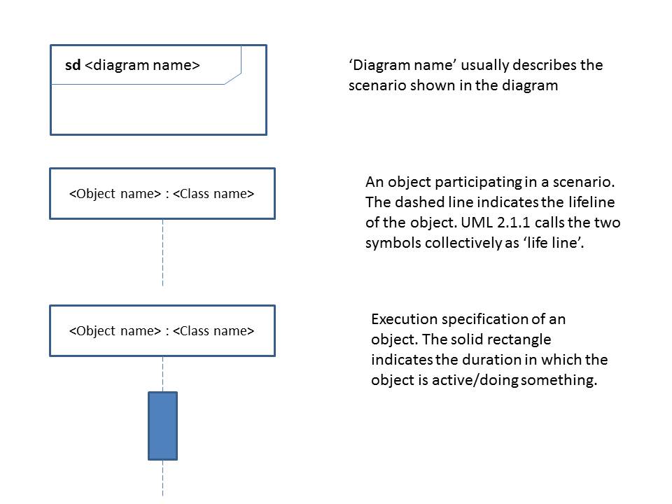
Figure 1: UML Sequence Diagram Notations - Part 1
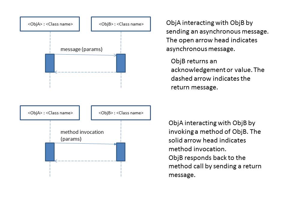
Figure 2: UML Sequence Diagram Notations - Part 2
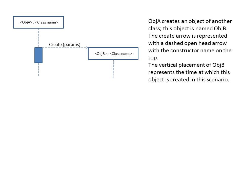
Figure 3: UML Sequence Diagram Notations - Part 3
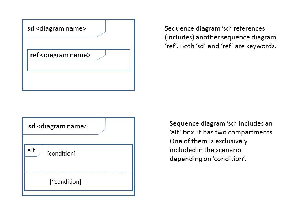
Figure 4: UML Sequence Diagram Notations - Part 4
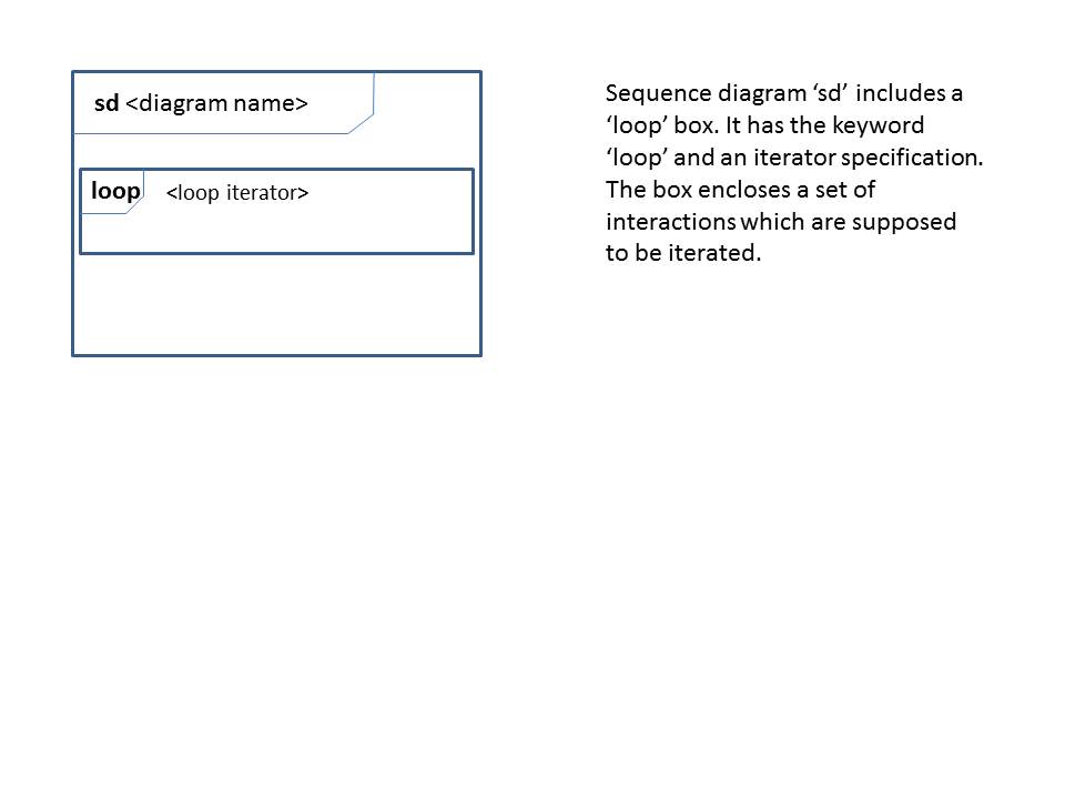
Figure 5: UML Sequence Diagram Notations - Part 5
Informal Semantics
Sequence Diagram: A sequence
diagram indicates the sequence of interactions between a selected subset
of
objects in the system. Typically, every sequence diagram individually represents
a particular scenario in the application domain. It may be a part or whole of a
use case, for example. Every sequence diagram is uniquely identified by its name
preceded by the keyword 'sd'. The entire diagram is represented inside a
rectangle with the diagram name at the top left corner. For convenience, some
designers (and some UML tools) do not include the rectangle.
The following rules are applied to verify the sequence diagram notation:
-
[SEQ.1]
The name of the diagram must be unique within
the system. The tag 'sd' appearing in front of the diagram name
is a keyword (see Figure 1).
-
[SEQ.2]
A sequence diagram may be referenced in
another sequence diagram using the keyword 'ref' followed by the
diagram name (see Figure 4).
Object: An object in a sequence diagram has the same
semantics of an object in an object diagram. It is represented as a rectangle
with the name of the object followed by a colon followed by the class name to
which the object belongs (e.g., s : Student). The object name and the class name
are not case sensitive. Sometimes, the entire name of the object (including
colon and the class name) may be underlined but it is a feature supported by the
OO analysis and design tool.
The following rules are applied with regard to the object notation:
- [OBJ.1] The name of each object must be unique within a sequence diagram.
- [OBJ.2] If there is more than one object from the same class in the diagram,
then every object of this class must be named; if there
is only one object from this class, the object name may be omitted.
- [OBJ.3] There is no ordering among the horizontal placement of objects in a
sequence diagram. So a user can place the objects horizontally in any order
depending on his/her convenience.
- [OBJ.4] The vertical placement of an object in a sequence diagram indicates when
that particular object comes into existence with regard to the scenario
described by the sequence diagram. Thus, the vertical position of an object
has a temporal (time-related) information associated with the object.
-
[OBJ.5] An
object in a sequence diagram is always associated with a life line
(described below).
Life line: A life line shows for how long an object
participates in a particular scenario (whether the object lives for the entire
scenario, or created newly in this scenario or is destroyed in this scenario).
It is represented as a vertical dashed line hanging from the object box.
The following rules govern the use of the life line symbol:
- [LIFE.1] A life line is always associated with an object. For this reason, UML
2.1.1. names the object and the dashed line together as 'life line'.
-
[LIFE.2] The
length of the life line indicates the duration in which the associated
object participates in the scenario.
- [LIFE.3] A life line must be
continuous. The dashed line indicates
that the object is idle during this time.
- [LIFE.4] Life lines are not labeled.
- [LIFE.5] If the object is destroyed in this scenario, then an "X" mark is placed
at the bottom of the life line for that object and the life line is
discontinued at that point.
- [LIFE.6] If the object is newly created in this scenario, then the object box is
drawn exactly on the horizontal line at the instance when it is created
and the life line of the object starts from there.
- [LIFE.7] If the object is created before this scenario starts, then the life line
starts at the beginning of this scenario. The object is assumed to have been
created somewhere before this scenario.
- [LIFE.8] If the object continues to live
after this scenario (i.e., it is not destroyed in this scenario), then the
life line of the object is left hanging at the bottom of the scenario.
Execution Specification: When
an object is active (doing something in the scenario such as sending a message
or receiving a message), a solid rectangle is placed on top of the object's life
line indicating that the object is active. UML 2.1.1. names this active portion
of an object as execution specification.
The following rules are applied to the execution specification symbol:
- [EXEC.1] An execution specification is always associated with an object and its life
line.
- [EXEC.2] There is no label for an execution specification.
Interaction: An
interaction in a sequence diagram represents a unidirectional communication
between objects. There are four types of interactions used in a sequence
diagram.
Asynchronous Message: This is represented by a solid
arrow with an open arrow head. Being asynchronous, the object sending the
message can do something else after sending the message; i.e., it does not wait
for a response from the receiving object. An asynchronous message may have
parameters. An asynchronous message is also called a 'stimulus'.
Method invocation: This is represented by a solid
arrow with a solid arrow head. It has the same semantics as in programming
languages for regular method calls and hence the sender will be blocked until
there is a response from the receiver. This type of message may have parameters.
Return message: This is represented by a dashed
arrow with an open arrow head. It may represent a simple termination or
confirmation from the receiver or it may also carry a return value. Additional
documentation is necessary to explain the nature of return value by this
interaction. Sometimes, a paired interaction may have a return variable specified in its label such as 'x =
getName()'. Generally, a return message is not labelled. Earlier versions of
UML use the label 'return'
on top of the arrow. Some UML tools still use this convention.
Create message: This is a special type of method
invocation which is represented by a dashed arrow with an open arrow head. It is
used when one object wants to create a new object in a scenario. While this type
of interaction has the same semantics as that of method invocation, the label on
this message must represent the constructor of the object being created.
The following rules are applied on interaction symbols:
- [INTER.1] Every interaction, except the return message, must be labeled. If it is a
method invocation, then the label is actually the name of a method
in the object at the receiving end of the arrow.
- [INTER.2] Every return message must be paired with one of the other three types of
interactions; in other words, a return message will not be sent without
being preceded by another interaction earlier. The semantics of the
application domain is necessary to determine which return message is
supposed to be paired with what interaction.
- [INTER.3] An interaction, except a
return message, can optionally have zero or more parameters. These
parameters are included in the interaction label.
- [INTER.4] An interaction, except a return message, may have a condition. If so, the
condition is written as a predicate enclosed in square brackets and is
placed at the beginning of the interaction label.
By placing the condition at the beginning of the message, it also indicated
that the condition is a pre-condition and hence must be checked before sending
the message.
- [INTER.5] An interaction may be sent from an object to itself (looping arrows).
-
[INTER.6]
An interaction arrow is generally drawn horizontally in which case the
interaction is assumed to be instantaneous. It may also be drawn as a
slanting arrow
in which case it is assumed to take significant time to complete.
The vertical displacement between the end points of the interaction arrow
indicates the duration for the interaction to complete.
- [INTER.7] Concurrent
interactions are drawn from the same object on the same horizontal
line extending towards two or more objects.
Alternate box: Interactions
in a sequence diagram occur in the same order as they appear vertically in the
diagram. So if an interaction A is placed above an interaction B, then A is said
to occur before B. Sometimes, a user may want to choose a few interactions
mutually exclusively from another set of interactions. In this case, the 'alt'
box is used (the term 'alt' is a keyword). An 'alt' box is similar to an
if-then-else block in a program. It encloses two sets of interactions, say A-set
and B-set with a condition specified inside the 'alt' box. If the condition is
true, one set of interactions, say the A-set, is included with the rest of the
interactions in the diagram. If the condition is false, then the other set, in
this case the B-set, is included with the rest of the interactions in the
diagram.
The following rules are applied on 'alt' box:
- [ALT.1] An 'alt' box encloses interactions between two or more
objects. The box must include the keyword 'alt' as a label.
- [ALT.2] It is not necessary to include all objects
participating in the scenario inside the 'alt'
box; i.e., only those objects affected by the condition of the
'alt' box are included in the box.
- [ALT.3] The 'alt' box must include two sets of interactions, and
each set must be labeled with the condition or its negation
exclusively (see Figure 4). Thus, these two sets of interactions
are mutually exclusive. It is possible that one of the two sets
may be empty, although it is practically useless if both the
sets are empty.
Loop box: A set of interactions
in a sequence diagram can be iterated, meaning that these interactions can be
specified to occur repeatedly based on some condition. This is similar to a loop
syntax in a program. The set of interactions to be repeated/iterated are
enclosed in a loop box. The box has the keyword 'loop' along with an iterator
specification. There is no standard syntax to specify an iterator. A sample
iterator specification may include a for loop syntax or a while loop syntax.
The following rules are applied on 'loop' box:
- [LOOP.1] A 'loop' box encloses a set of interactions
overlapping with one or more
objects. The box must include the keyword 'loop' as a label.
- [LOOP.2] It is not necessary to include all objects
participating in the scenario inside the 'loop'
box; i.e., only those objects affected by the condition of the
'loop' box are included in the box.
- [LOOP.3] The 'loop' box must have an iterator specification
indicating the loop index or loop variable and how it changes.
References:
- Hans-Erik Erikson et al., UML 2 Toolkit, Wiley
Publishing Company, 2004, ISBN: 0-471-46361-2.
- Russ Miles and Kim Hamilton, Learning UML 2.0, O-Reilly, 2006,
ISBN: 0-596-00982-8.
- Alan Dennis et al., System Analysis & Design
with UML, Wiley, 2012, ISBN: 978-1118037423.
- Bernd Bruegge and Allen
H. Dutoit, Object-Oriented Software Engineering Using UML, Patterns and Java
(3rd edition), Prentice Hall, 2009, ISBN: 978-0136061250.
- UML Standard
documents published at the Object Management Group (OMG) web site:
www.omg.org/spec/UML.
- James Rumbaugh et al., The Unified Modeling
Language Reference Manual, Addison-Wesley, 1999, ISBN: 0-201-30998-X.
-
Hassan Gomaa, Software Modeling and Design, Cambridge University Press,
2011, ISBN: 978-0-521-76414-8.
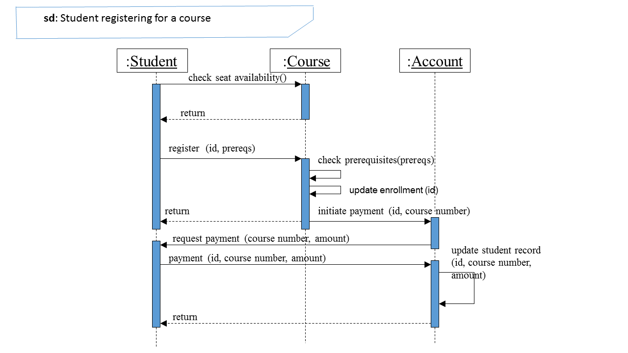
Sample sequence diagram: