CS 743 - Software Verification and Validation
Fall 2019
Informal Semantics for UML Class Diagram
This document describes informal semantics of UML 2.0 (Unified Modeling
Language version 2.0) Class diagrams. The document is intended to verify UML
class diagrams and not to describe how to draw a class diagram. Consequently,
the readers should refer to UML manuals or books for a detailed treatment of UML
notations and how to use them.
UML Class Diagram
A class diagram in UML describes the classes of the application
being modeled and the relationships among these classes. It provides the structural
and static view of the entire system. Depending on the level of
abstraction, a class diagram may describe only those classes selected
or identified in the application domain or could describe every class
that will eventually be implemented. A class icon in the diagram
may describe only partial information about the class; e.g., names and types of
attributes and
names of operations. In order to make the diagram look simple and elegant, most
users provide only names of attributes and operations and include a
pointer to the documentation page that contains additional details
about these attributes and operations.
The relationships among the classes can be broadly classified into
three categories: association, aggregation and specialization
(implemented through inheritance).
Notations - Summary
An UML class diagram is composed of the following notations:
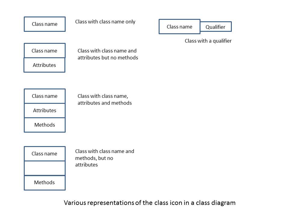
Figure 1. Various representations of class icon in a Class Diagram
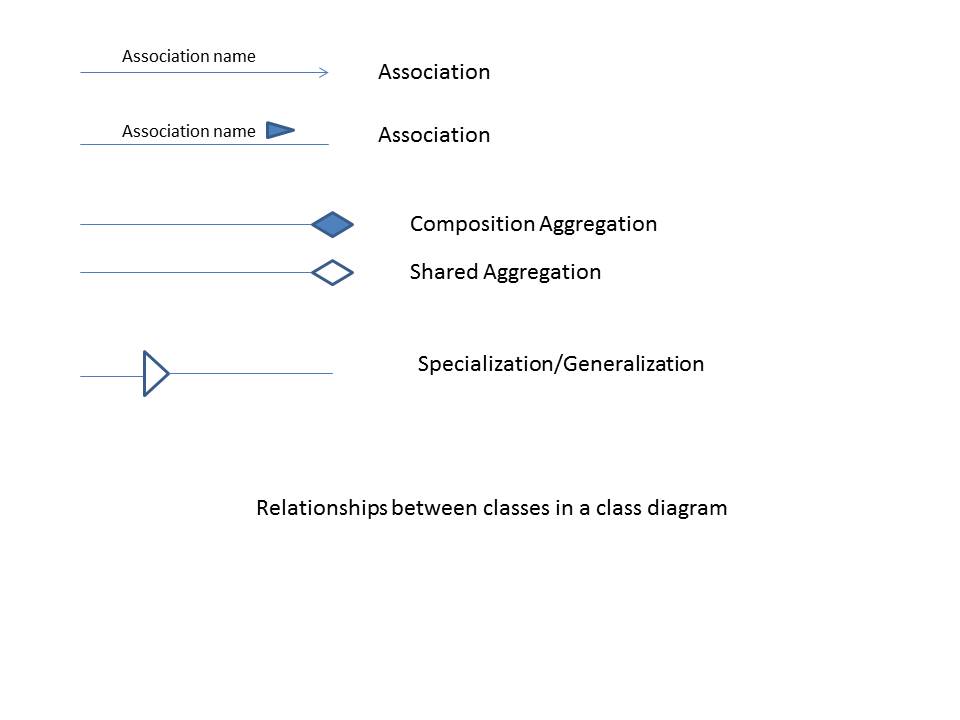
Figure 2. Symbols representing relationships between
classes in a Class Diagram
Informal Semantics
Class: A class represents an abstraction of a
collection of objects (equally treated as the type of the same
collection of objects). Class is the modeling and programming entity,
that is instantiated later into a set of objects at run-time. The
objects instantiated from a particular class will all behave
identically; these behaviors are defined by the methods (or
operations) of the class. The structure of a class is defined by a set
of attributes which also characterize the state of an object
instantiated from the class.
A class may have an optional qualifier. If specified, the qualifier is generally
one of the attributes of the class. The qualifier is used to identify a unique
object/instance of the class when multiple objects/instances are used in a
relationship with another class.
The name of the class must be present. The attributes and methods of the class
need not be shown in the diagram. Even if they are specified, they do not need
to be fully specified in the diagram. However, for verification with respect to
the application domain, complete details of all attributes and methods are
needed. These can be specified in a separate document outside the class
diagram.
The following rules are applied to verify a class notation:
- [CLASS.1] Each class has a unique name within the diagram. If a class name
appears more than once in the same diagram, then logically these icons are
combined into one class.
- [CLASS.2] The class name compartment may also include additional information
such as whether or not the class is abstract, persistent, author information
etc.
- [CLASS.3] A class icon may or may not have attributes or operations.
- [CLASS.3.1] The name of an attribute is unique within the class.
- [CLASS.3.2] A method is uniquely identified by its signature. Thus,
overloaded methods may have the same names but different
signatures.
- [CLASS.3.3] The set of names of attributes and the set of names of methods
are mutually exclusive.
- [CLASS.3.4] No attribute can have the same name as that of the class.
However, constructor methods may have the same name as that
of the class.
- [CLASS.3.5] An attribute or a method within a class may optionally have a
visibility symbol ('+', '-' or '#') attached as a prefix. Refer to
[1,5] for description of these symbols.
- [CLASS.3.6] An attribute may have an initial value specified.
- [CLASS.4] A class may optionally have a qualifier attached to it. If there is a
qualifier attached to a class, its name is generally one of the attributes
of the class.
- [CLASS.5] A class must be connected to at least one other class in the
diagram. Unconnected classes are not useful.
- [CLASS.6] Two classes may optionally be connected by a constraint symbol (a
dashed line) with the constraint written on top of this symbol.
Association: An association describes a semantic
dependency between two classes. The semantics dependency can range
from simple message passing to enclosing one class within another. The
details of the semantic dependency may not be explicit in the
diagram.
The following rules govern the use of the association symbol in a
class diagram:
- [ASSO.1] Each association may optionally have a label. Though unnamed
associations are somewhat vague for the designers and implementers,
UML does not require a label for an association.
- [ASSO.2] If present, the label of an association uniquely determines the
association itself.
- [ASSO.3] An association is generally uni-directional; the direction of the
association is implied by the meaning of the label; so, the designer
is expected to choose a suitable name for the association that is
meaningful in the current application. An arrow is attached to the association
label or to one end of the association in order to indicate the direction
explicit. See Figure 2 for the two different styles of the association symbol.
- [ASSO.4] An association must connect exactly two classes; it is possible
for an association to connect the same class on either end in which
case it is called a recursive association.
- [ASSO.5] There can be any number of distinct associations between the same
pair of classes.
- [ASSO.6] An association may optionally have a cardinality on either end of
the association. A cardinality symbol (also called multiplicity in
UML) is of
the form 'n..m' where n and m are numbers, n >= 0, m >= 0 and m >= n.
When an association from a class A to B has a cardinality of n..m at
the end close to the class B, it is read as "every object of class A
is associated with n to m objects of class B at the same time".
The symbol '*' can also be used in place of 'n..m', which means 'zero or more'.
- [ASSO.7] An association may optionally have a role. A role symbol is a
label close to the participating class. Consequently, each class in
the association may have a role.
- [ASSO.8] An association may optionally have one or more constraints enclosed in
curly brackets and placed near the association. Sometimes, the
constraints may be imposed on more than one association. See [1]
for examples on placing constraints on associations.
Aggregation: An aggregation relationship between a
pair of classes indicates that an object of one class encloses an object of the other
class. The class
at the diamond end of the aggregation symbol is an aggregate and the
other class is a component. For example, the class "Polygon"
aggregates the class "Line", in which case the diamond end of the
aggregation symbol must touch the class "Polygon". An aggregation is
also an association; however, there are some differences. See [1]
for more details on the differences.
There are two types of aggregation - shared aggregation (represented by
hallow diamond) and composition aggregation (represented by filled
diamond). In shared aggregation, the component (the one at tail end of
the aggregation arrow) can be shared by other aggregates. In
composition aggregation, the component is not shared and is
exclusively used by the aggregate to which it is connected.
The following rules govern the use of the aggregation symbol in a
class diagram:
- [AGGR.1] An aggregation is an association and hence it may be labeled. It
may also include cardinalities.
- [AGGR.2] If class A aggregates class B, then A must contain at least one
attribute b whose type is B. The attribute b in A must be shown
in the diagram.
- [AGGR.3] In composition aggregation, the component class (the one at the
tail end of the aggregation arrow) cannot be shared by any other aggregate.
- [AGGR.4] An aggregation relationship cannot be cyclic.
Specialization: The specialization symbol
connects a subclass (or a specialized class) to its superclass (or a
generalized class). The base of the triangle should be connected to
the subclass.
The following rules are applicable for the specialization symbol in a
class diagram:
- [SPEC.1] The specialization symbol is generally not labeled. A label on a
specialization symbol can appear only when there is a common parent
for several (two or more) subclasses. In this case, the label should
be one of the following: "disjoint", "overlapping", "complete" and
"incomplete". This label indicates the constraint on the subclasses.
- [SPEC.2] If the subclass icon contains attributes and/or operations, the
inherited attributes and/or operations are not listed in the
subclass, unless they are overridden/redefined in the subclass.
- [SPEC.3] A specialization relationship cannot be cyclic.
References:
- Hans-Erik Erikson et al., UML 2 Toolkit, Wiley
Publishing Company, 2004, ISBN: 0-471-46361-2.
- Russ Miles and Kim Hamilton, Learning UML 2.0, O-Reilly, 2006,
ISBN: 0-596-00982-8.
- Alan Dennis et al., System Analysis & Design
with UML, Wiley, 2012, ISBN: 978-1118037423.
- Bernd Bruegge and Allen
H. Dutoit, Object-Oriented Software Engineering Using UML, Patterns and Java
(3rd edition), Prentice Hall, 2009, ISBN: 978-0136061250.
- UML Standard
documents published at the Object Management Group (OMG) web site:
www.omg.org/spec/UML.
- James Rumbaugh et al., The Unified Modeling
Language Reference Manual, Addison-Wesley, 1999, ISBN: 0-201-30998-X.
-
Hassan Gomaa, Software Modeling and Design, Cambridge University Press,
2011, ISBN: 978-0-521-76414-8.
Sample Class Diagram:
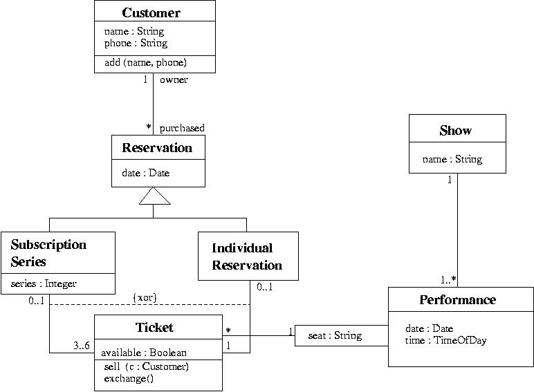
Figure 3. Sample Class Diagram taken from reference #6.